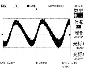
Ripple is the alternating component of voltage from a rectifier. It is a AC factor that residually retained when the rectifier convert ac input power to dc output power. Lower ripple means the DC output is more steady. Using DC output with low ripple for plating can get a better quality. The value of the ripple depends on the design of the rectifier and the charaecteristics of the componenet used. Ripple measurement is an AC measurement at the output of the DC rectifier at rated load and 25 oC ambient temperature. The measurement is always specified as millivots peak-to-peak value.
 Demonstration of ripple measurement |
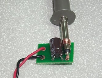 Probe connection across the terminal should be as short as possible |
The measurement must be carefully made in order not to induce error voltages in the test equipment. Conventioal ground clip on an oscilloscope probe should never be used sinces it acts like an antenna or inductive pickup loop, creating an extraneous voltage which is not part of the output noise of the rectifier. To eliminate this noise pickup, the connection of the probe that across the output terminals should be as short as possible. The probe with an external ground band or ring can be used. The measureing method is pressing the band directly against the output common terminal of the power converter while the tip contacts the voltage output terminal during measurement.
Below is the measuring method commonly use:
- Switch on the DC rectifier with maxinum current output.
- Connect the DC output terminal to the 47uF capacitor and Scope probe using the twisted 16 AWG copper wire.
(As shown in the digaram below.)
- Set the oscilloscope to the following setting:
- Coupling: AC coupling
- Volt/div: 10mV/div
- Time base: 5ms/div
- Trigger: Auto triggered
- The waveform found in the oscilloscope is the ripple waveform. Its peak-to-peak value is the ripple of the DC output.